
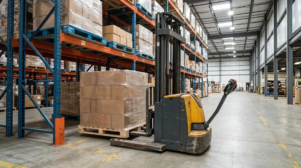
A pallet stacker has to fit the load, the rack and the route between them. Clearing a doorway does not guarantee that a truck can enter the pallet, turn into an aisle or place the load at the required height. The checks involve different measurements, and specification sheets do not always use the same terms.
Start With the Job, Not the Truck
The useful starting point is the job itself: the pallet and load, the rack position, the route between pickup and placement, and how often the truck will move them. A truck that fits one doorway may still be unsuitable for the pallet or turning space beyond it.
To keep the checks concrete, this guide uses one set of assumed measurements throughout. A 1,200 × 800 mm pallet carries a 1,100 × 700 mm load, with the 700 mm side running across the pallet’s 800 mm width. The load sits 100 mm off-center. The target rack support surface is 4,500 mm above the floor. These numbers show how to reason through a fit check. They are not a specification, a clearance standard or a customer case.
A stacker selection guide covers the main equipment layouts. The measurements below help assess whether a particular configuration fits a specific job.
Which Pallet Stacker Dimensions Matter?
Dimension names and measurement bases vary by manufacturer, so similarly named figures are not automatically comparable. The specification notes and drawing identify what each number measures.
| Measurement | Where it matters | What to verify |
|---|---|---|
| Truck length | Turning, parking, trailer loading and space near doorways | Whether forks are included; platform folded or deployed; measurement reference points |
| Overall truck width | Doorways, aisles and rack clearances | Whether support legs, guards or other widest components are included |
| Fork dimensions | Pallet entry, load support and clearance from pallet members | Fork length, single-fork width, outside width, spacing and minimum fork height |
| Support-leg dimensions | Pallet entry and clearance near racks or loads | Inside and outside width, leg length and restrictions on pallet or load overhang |
| Lowered mast height | Travel beneath doors, beams or trailer openings | Whether it describes the mast alone or the highest point of the complete truck |
| Lift and raised heights | Rack access and overhead clearance while lifting | Maximum fork height, overall height with mast raised and the configuration each figure describes |
The diagram below shows common measurement points on one simplified support-leg layout. It is a visual key, not a dimension drawing; the points and terminology on the selected truck may differ.
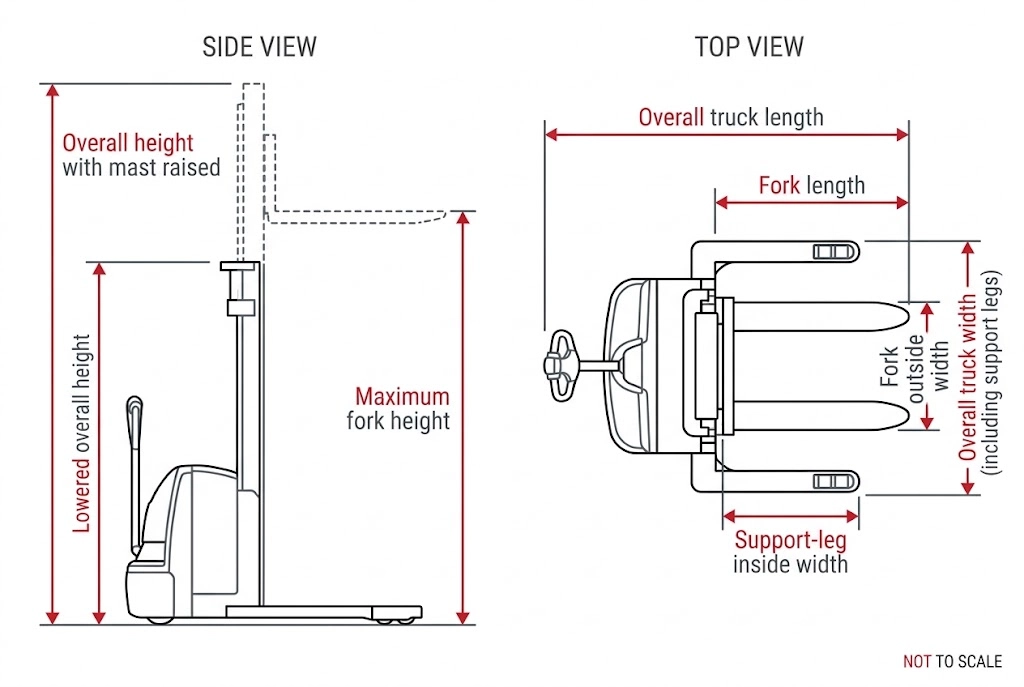
A specification may list maximum fork height, free lift, lowered mast height and overall height with the mast raised as separate fields. These terms are not interchangeable. Confirm each measurement point and mast configuration on the selected truck’s specification sheet or dimension drawing.
Check Forks, Pallets and Support Legs Together
A pallet’s outside length and width do not show whether a stacker can enter it. The underside construction, fork openings and entry direction determine the clearance available to the forks and, where fitted, the support legs.
Measure the pallet at the fork openings
Inspect the underside and record the width and height of each opening, the position of blocks, stringers and bottom boards, which sides allow entry, and the orientation used during travel and storage. Check for repairs or damage that reduce an opening.
Compare those measurements with the truck’s fork length, width, spacing and minimum height. Forks that enter an opening may still touch a bottom board during lifting or withdrawal. Confirm that the forks can travel far enough under the load and support it as intended.
The example shows how load position affects clearance. A 700 mm load on an 800 mm pallet leaves 50 mm on each side when centered. Moving its center 100 mm off-center produces a 50 mm overhang on one side and 150 mm of clearance on the other. The widest point is now 50 mm past the pallet edge in that direction, and that is the figure to carry into every doorway and aisle check later in this guide.
Labels such as “two-way” or “four-way” can help describe entry direction, but inspect the actual pallet. Its construction, blocks, deck boards and repairs may limit access for a particular truck layout.
Trace the support-leg path
On a stacker with support legs, compare the gap between the legs and their length with the pallet’s outside dimensions, bottom structure and any load overhang. Then trace the legs’ path from pallet entry to the working position. Rack uprights, floor-level beams and neighbouring loads can obstruct the legs even when the forks fit.
A counterbalance layout does not use the same front support legs, so it may approach some pallet and load arrangements differently. The straddle and counterbalance stacker comparison explains this layout difference. The drawing for the selected truck determines actual clearance.
Include the load’s full outline
Measure the load separately from the pallet. Record any overhang on each side, offset from the pallet centre, irregular shape or change in width higher up the load. A load may clear a doorway at floor level and still contact a rack upright as it turns. The widest point, not necessarily the pallet edge, determines the clearance check.
Understand the Main Height Measurements
“Stacker height” can refer to different measurements. A quotation that gives only one height may not answer whether the truck can travel through an opening and reach a storage position.
| Term | Question it helps answer | What to confirm |
|---|---|---|
| Lift height or maximum fork height | Can the forks reach the required placement position? | Whether height is measured to the top of the forks or another point |
| Lowered mast height | Can the truck travel under a low obstruction with the mast lowered? | Whether the figure describes the mast or the complete truck’s highest point |
| Overall height with mast raised | Is there overhead clearance while lifting? | Which parts are included, such as the mast or load backrest |
Return to the example. The 4,500 mm figure is the height of the support surface, not the height the forks must reach. The pallet has to be placed and the forks withdrawn without contacting the beam, so the required fork height depends on the pallet, beam and truck geometry. The pallet and load also extend above the support surface, which matters for the rack opening and for anything hanging overhead. The top of the load, not the support surface, is the figure to compare against the clearance above the rack position.
Do not calculate one height value from another unless the manufacturer provides a drawing or an explicit relationship for the selected configuration. Two mast options with the same maximum fork height can have different lowered heights or different heights when extended.
For travel clearance, measure the highest point of the complete truck in its travel state, including lights, guards and other protruding parts. Compare it with the lowest doorway, beam or overhead obstruction on the route. If a specification uses a field such as “mast height at maximum lift,” confirm which physical point it measures — do not assume it is the same as “overall height with mast raised.” Request the drawing for the exact mast and truck configuration if the distinction affects fit.
Measure the Rack Position and Required Fork Height
A rack drawing may show a nominal beam height, but the installed rack is what the truck must work with. Measure the highest pallet support surface, the clear opening between levels and the lowest obstruction above the position. Then work through the placement sequence for the actual pallet and beam.
The support-surface height, the fork height needed to place the pallet and the top of the load are three different values. In the example, the support surface is at 4,500 mm, but the forks need enough movement above that to set the pallet down and withdraw, and the load extends higher still. The exact placement sequence depends on the pallet, beam and truck geometry, so confirm the target fork height for the actual configuration rather than adding a universal clearance figure.
- Measure the target: record the height of the pallet support surface above the floor.
- Measure the pallet and load: record their combined height and note any overhang or uneven shape.
- Check the rack opening: measure the clear space between levels and any obstructions that reduce it.
- Consider placement and withdrawal: check how the pallet will be placed and how the forks will clear the rack.
- Confirm the mast option: compare site measurements with the manufacturer’s maximum fork height and raised overall height.
There is no single clearance allowance that applies to every rack, load and truck. Confirm the required clearance for the installation with the equipment supplier and the people responsible for the racking and site procedures.
Check Doorways, Aisles and Turning Space
A doorway check and an aisle check are different. For a straight passage, compare the doorway’s clear width and height with the complete truck, pallet and load in their travel configuration. For a turn, truck length, turning geometry, pallet orientation and available space before and after the turn also matter.
The example gives two possible widths to check, depending on pallet orientation. If the pallet travels with its 800 mm side across the doorway, the pallet-and-load envelope in that direction is 850 mm because the load overhangs by 50 mm. If it travels with its 1,200 mm side across the opening, the envelope is 1,200 mm. Compare the chosen orientation and the truck’s outline together; do not simply add the truck width to the pallet width.
At each doorway
- Measure the narrowest clear width and lowest clear height.
- Include the forks or support legs, pallet and load in the travel configuration.
- Check the platform position for stand-on models.
- Measure the approach and exit space needed to line up for the next maneuver.
- Note door tracks, guards, pipes or other parts that reduce the opening.
Along each aisle
Measure the narrowest usable width between actual obstructions, including rack protectors, columns and parked equipment. Note whether the pallet travels lengthwise or widthwise and whether the truck must turn inside the aisle. Nominal rack spacing may be greater than the space available to the truck and load.
Turning radius (often labelled Wa) and working aisle width (often labelled Ast) describe different measurements. Wa describes a turning measurement under a stated method. Ast describes the aisle space needed for a specified truck, pallet and maneuver. Wa alone does not establish Ast. Use an Ast figure only when its stated pallet size, orientation and truck configuration match the job. The forklift aisle-width guide explains these terms and provides a site measurement method.
Confirm Capacity for the Actual Load and Height
A rated capacity applies to stated conditions. Load weight alone does not describe those conditions. Load center, dimensions, weight distribution, lift height and attachments can affect the capacity available for a particular configuration.
OSHA’s guidance on truck data plates and load composition explains how capacity relates to specified load conditions and how load position or attachments can affect a rating. Its examples address powered industrial trucks and do not replace the capacity information and instructions for a particular stacker. Applicable requirements vary by jurisdiction.
When asking for capacity confirmation, provide the combined weight of the pallet and load, load dimensions and weight distribution, load center if known, fork-entry direction, target lift height, and the mast, forks and any attachment required. Ask for the load curve or written capacity confirmation for the selected configuration at the target height, actual load center and attachment setup. If the specification sheet does not show the relevant capacity information, request it. The forklift capacity guide provides more background on load center and rated capacity.
Common Measurement Mistakes
A dimension can be correct on paper and still be the wrong number for a particular clearance check. These are the comparisons most likely to mislead:
- Using chassis width as doorway width: forks, support legs, pallet or load can extend beyond the chassis.
- Comparing different configurations: mast, fork and platform options can change the relevant dimensions.
- Assuming height terms are interchangeable: verify field definitions and measurement points.
- Measuring from a rack drawing alone: installed protectors, beams and overhead services can reduce clearance.
- Checking the doorway but not the approach: the truck may pass through but lack room to line up or turn.
- Using turning radius as aisle width: check Ast for the actual pallet orientation and truck configuration.
- Checking only the pallet: load overhang and weight distribution affect clearance and capacity.
- Using rated capacity without its conditions: confirm load center, lift height, attachments and configuration.
Measurement Checklist
Once the load, route, rack position and capacity conditions have been considered, this summary brings the site information together for a configuration check.
| Area | Information to record |
|---|---|
| Pallet and load | Length, width, height, combined weight, underside construction, entry direction, overhang and weight distribution |
| Rack position | Highest target support-surface height, rack-level opening and overhead clearance |
| Route | Door clear width and height, aisle width, turning space, floor condition, ramps and thresholds |
| Truck configuration | Length, width, fork dimensions, support-leg dimensions, platform state and mast option |
| Capacity conditions | Load center, target lift height, attachment and capacity confirmation for the selected configuration |
| Use pattern | Operating hours per shift, movement frequency and typical travel distance |
Photos of the pallet underside, rack opening, doorway and route can clarify details that are difficult to describe. Floor and ramp conditions are relevant to a suitability check, but do not establish that a particular stacker is designed for ramp work.
Sources and Scope
This guide describes a measurement and comparison process. Manufacturers may define dimension fields differently, so check the drawing and instructions for the exact configuration. OSHA references below provide U.S. workplace guidance; applicable requirements vary by location. Follow the truck manufacturer’s instructions and site operating procedures.
“`